 ..the cat came back..
Recently Written
- Kiosk Browser Grows Up, Goes Pro
- Android App: Simple Kiosk Browser
- Widget, it’s got a widget…
- LinkUSB(i) and 1-Wire setup
- I am an IAMS cat
- LG TV Serial Control
- Tivo Return to UK Via Virgin Media
- Another Android Security Update
- Pictures from Computex 2009
- Pull That Squidgy iPhone application
- Extra Cupcake, Still No Latitude
- G1 Assault on battery
- Everywhere you go, always take the weather with you
- Pachube dials without the heartache
- Dynamic Dials Disclosed
- Gratifying Graphic Gizmos
- Current Cost Capers
- One Wireduino made easy
- WordPress tweetbacking
- What the UK VAT Reduction really means
Categories
- 1-Wire

- android
- arduino
- computex
- freerunner
- hardware
- image builds
- iphone
- kiosk
- learning
- linux
- neo 1973
- openmoko
- opensource
- personal
- software
- VoIP
Archives
- November 2011
- July 2011
- May 2011
- January 2011
- October 2010
- November 2009
- July 2009
- June 2009
- May 2009
- April 2009
- March 2009
- February 2009
- January 2009
- December 2008
- November 2008
- October 2008
- September 2008
- August 2008
- July 2008
- June 2008
- April 2008
- March 2008
- February 2008
- January 2008
- December 2007
- November 2007
- October 2007
- September 2007
Admin
Search
Feb
18
USB Controlled RGB Blob
18 years ago, mid-February | 6 Comments
I recently came across a little project which would turn on an LED box when there was mail your gmail account. I thought it was quite interesting and, since I’d had an Arduino Diecimila in my laptop bag for about 6 months and not touched it, I decided to replicate it. The idea was simply to get used to how the Arduino board worked, the project in itself isn’t exactly going to push anyone to their limit. I was right, the code was basically in the examples there was nothing to do. Since we’re selling our house lots of my electronics development stuff has ended up in the loft. I went for a rummage and found some little RGB light globes that a local garden centre had been trying to sell off cheaply at a couple of Euros each. Undoing the screws on the base of the globe revealed a very simple 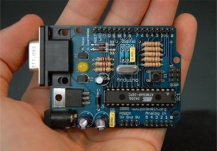
design, I’d just need to tap into the LEDs and disconnect the chip they used. Before any of this was going to happen I needed to build some sort of prototype to at least be sure that the concept was going to work. Since I didn’t have any RGB LEDs or even one of each red, green and blue I had to settle for a small LED board that had come from an old piece of equipment that I’d bought, literally, just for the parts. There was a slight problem. The led board was red, green and errm… orange. It didn’t really matter at this stage, I was only proving the code and making sure that I could get the whole idea to work before destroying the perfectly useless light globes.
The software side was also fairly straight forward too. In the end I used the SimpleMessageSystem library to handle the serial data since I kept running into issues with the standard serial I/O routines. The SimpleMessageSystem routines basically use white space as variable separators and a <CR> to signify the end of input.
Each of the colour channels can have a value between 0 (zero) and 255 which gives a lot of variation. There’s also the option to pulse the mixed colours.
Initially I was just going to have the 3 LEDs change to their relative brightness but then I hit on the idea of having them fade up and down to the correct value. I have to say it looks much better with the gradual change, although I might just add the option of selecting either gradual or instant to the parameter list.
Now, with a simple command, I can set the RGB value of my light globe.
./rgb-globe -l -b 9600 -p/dev/ttyUSB0 -s “1 255 50 0”
The original code for the command line application came from Tod Kurt and was written to be able to send serial data to the Arduino. I did make some modifications, including a couple of virtual slappings of Tod for using strcpy – I still don’t understand why people don’t pretend that function just does not exist.
I’m considering writing a small GTK application that just has a colour picker to select colours, but that would be in addition to the command line application since this is designed to be used from things like scripts or mail and IM notifications or, as I suspect mine will, build status information for my Openmoko buildhost. The only real issue at the moment is that it’s really not bright enough, I think I need to rethink the orb – maybe it’ll be better at night…
![]()
![]()

Tagged with: arduino • hardware • linux • software
February 18, 2008 16:46
Comments
6 Comments so far
Current Electricity Use (15min)
iPhone/Webkit RSS Reader
Links
- automated home
- Automated It Technology News
- awooga!!!
- LinITX
- My Acer page
- My Asterisk pages
- My Work in progress (old)
- Noble Race Car
- openmoko / neo 1973 wiki
- planet openmoko
- Spadgecock Cumpants
Tags
1-Wire android api Apple arduino currentcost DDAR development DVD FIC freerunner G1 google Google Phone gphone gprs GPS hardware image image builds inspiration iphone jailbreak kiosk linux Mac monitoring Music neo 1973 Nokia openmoko opensource OSX Pachube personal qtopia rhubarb rikki Rio slimp3 slimserver software tracking Trolltech u-bootTwitpic
Graphy Stuff


I found your site on technorati and read a few of your other posts. Keep up the good work. I just added your RSS feed to my Google News Reader. Looking forward to reading more from you.
Chris Moran
You mentioned you are using Simple Message System on your Diecimila. If you get my script package you
can have full control of IO & PWM. AD is scaled to mV & formatted for import to most spreadsheets. See http://207.14.167.161 for the package, SMS1.tgz. Then you could control yer 3 leds with ‘writePWM-1 pin# 0-255’ and a whole lot more. Put a bunch of these commands in a textfile & ‘source’ that file.
Sorry, my mini-website isn’t 24/7, it only works when my PC is booted, so keep trying.
My shellscript package is now available 24/7 at http://user.cavenet.com/rolandl
Now with a GUI via the Xdialog command.
[…] a very long time now I’ve been playing with the Arduino boards but it wasn’t until I recently discovered some DS1820 1-wire chips in […]
This was very similar to my first arduino project. I started with a common cathode RGB led controlled via 3 pwm channels. I made an oragami cube to diffuse it even more. I created a number of color cycling ‘patterns’, along with random cycling, both instant and fading. Finally for added fun I whipped up a processing sketch that would send the color of the pixel under the mouse to the arduino. I cut out a paper cube and had a ‘magic pixel’ that was a pretty close match of the pixel under my screen.
I like the idea of picking the colour of the led from the screen, much more interactive for the user. I have to admit to not having taken a look at processing at all but from what I’ve seen I probably should. Did you have a url for your project?